PCBA Test
PCBA test refers to the detection of electrical continuity and input and output values of PCBA. In the design of PCB boards, there are numerical relationships between different test points, such as voltage and current. To verify whether the PCB board meets the design requirements, it is necessary to use professional test equipment to test points. PCBA test is a key to ensure the quality of production and delivery. The FCT test fixture is made according to the test points, procedures and test steps designed by the customer, and the PCBA board is placed on the FCT test stand to complete the test.
PCBA Test Principle
Connecting the test points on the PCBA board through FCT testing jigs and forming a complete path to link the computer and burner and upload MCU program. The MCU program will capture the user’s input actions (such as long-pressing the switch for 3 seconds), and control the on and off of the circuit (such as LED flashing) or drive the motor to rotate through calculations. To complete the test of the entire PCBA board by observing the voltage and current values between the test points on the FCT test jigs, and verifying whether these input and output actions are consistent with the design.
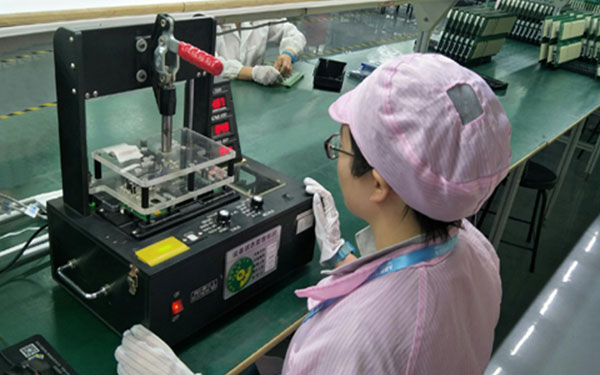
PCBA Test Jigs
For the testing of large quantities PCBA boards, it is necessary to have a test jig to improve the productivity. When the power is turned on, the key data such as voltage and current in the circuit are obtained and displayed on the display screen of the test jig to achieve the purpose of rapid detection. When the customer designs the PCB board, the engineer will consider its test plan and reserve PCB test points, then issue a professional test document or test plan to the manufacturer.
PCBA testing is an indispensable and important part in the entire PCBA manufacturing supply chain. Quality is controlled from the final data results. In standardized design and manufacturing management, PCBA testing must be recommended, considered and implemented.