
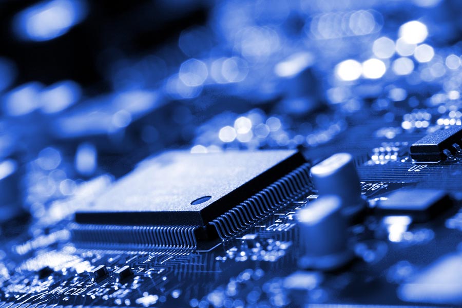
This article will summarize the differences between the integrated circuit (IC) and printed circuit board (PCB).
1 PCB Basics
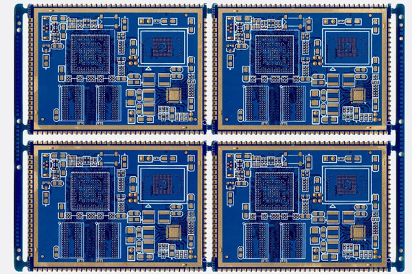
1.1 Composition of PCB
-Wiring the Pattern: the wiring is a tool to conduct the components, and a large copper surface is additionally designed to ground and used as the power. The wiring and the pattern are made at the same time.
-Dielectric: commonly known as substrate, is used to maintain insulation between the wiring and layers.
-Through-hole/via: the wiring of more than two layers can be switched to each other, and the larger one is used as a part plug-in. Usually, electroless plated through holes are used as surface mounting positioning and fixing screws for assembly.
-Solder resistant/Solder Mask: not all copper surfaces have welded the parts by tin. Therefore, in areas without tin, a material (usually epoxying) is printed to avoid short circuits. According to different processes, it is divided into green oil, red oil and blue oil.
-Legend/Marking/Silkscreen: not necessary. Its main function is to mark the name and position frame of each part for easy maintenance and identification after assembly.
-Surface Finish: copper surface in the general environment is easy to oxidize, leading to poor soldering, so it is necessary to make a copper surface protection. The methods of protection include HASL, ENIG, Immersion Silver, Immersion Tin, and OSP, which have their advantages and disadvantages, and all of them are generally called surface treatment.
1.2 Characteristics of PCB
-High density: For decades, PCB high density has been developed with the development of integrated circuits and integrated mounting technology.
-High reliability: Through a series of inspections, tests and aging tests, the PCB can be reliably operated for a long period of time (usually 20 years).
-Designability. For requirements based on the PCB performance (electrical, physical, mechanical, etc.), the PCB design is standardized with short time and high efficiency.
-Productivity. Modern management ensure the consistency of product quality through standardization, scale and automation.
-Testability. Establish complete testing methods and testing standards, and use various testing equipment and instruments to test and evaluate the eligibility and service life of PCB products.
-PCB Assembly. PCB products can not only easily assemble various components in a standardized way, but also assemble various components into larger components, systems, and even complete machines.
-Maintainability. Because PCB products and components are manufactured in a standardized design and scale, these components are also standardized. Therefore, once the system fails, it can be quickly replaced, and the system can be restored easily and flexibly. Of course, more examples can be given, such as system miniaturization, lighter weight, and faster signal transmission speed and so on.
2 IC Basics
2.1 Composition of IC
An integrated circuit is a microelectronic device or component. The transistors, diodes, resistors, capacitors, and inductors required in the circuit are connected to each other through a certain process, fabricated on a small semiconductor chip or dielectric substrate, and then packaged in a shell, and finally, become a microstructure with the functions required by the circuit. All components are structurally integrated into integrated circuits.
2.2 Characteristics of IC
Simple circuit. Because of the use of integrated circuits, the design, debugging and installation of the whole machine circuit are simplified, especially after the adoption of some special integrated circuits, the whole machine circuit appears more simple.
Cost-effective. Compared with discrete electronic component circuits, the overall circuit performance of the integrated circuit is higher, and the cost and price are lower. The high gain and small zero drift of the integrated operational amplifier circuit are unmatched by discrete electronic components.
High reliability. The integrated circuit has the advantage of high reliability, which improves the reliability of the whole circuit and improves the performance and consistency of the circuit. In addition, with an integrated circuit, the solder joint in the circuit is greatly reduced, and the possibility of virtual welding is decreased, which makes the whole circuit more reliable.
Less energy consumption. Integrated circuits also have the advantages of small power consumption, small volume, low price and so on. Circuits with the same function consume much less power with integrated circuits than with discrete electronic components.
Low failure rate. The failure rate of the integrated circuit is lower than that of the discrete circuit, so the failure rate of the whole circuit is reduced.
In short, the integrated circuit has the advantages of small size, lightweight, less lead wire and welding joint, long life, high reliability, good performance, and low cost, which is convenient for mass production. When electronic equipment is assembled by an integrated circuit, its assembly density can be increased by tens to thousands of times than that of transistors, and the stable working time of the equipment can be greatly increased.
3 The Difference Between PCB and IC
An integrated circuit is a miniaturized electronic circuit. The internal chip is very small and it is difficult to connect directly to the PCB, while the IC can be easily connected to the PCB. The motherboard inside the northbridge chip and the CPU is called IC, and its original name is also called an integrated block.
PCB is used in almost every electronic device. If there are electronic parts in a device, PCBs are mounted on PCB of all sizes. Besides fixing small parts, the main function of PCB is to connect each other.
IC is welded to PCB, where is the carrier of IC. In short, an integrated circuit is the integration of ordinary circuits on a chip, it is a whole. Once internally damaged, the chip will also be damaged. The purpose of PCB is to connect integrated circuits and discrete components to form a larger working circuit. The PCB itself can solder components, and when it is damaged, it can replace components. Before PCBs were used, components were connected together by wires, using a solution called “point-to-point” wiring. Compared with PCBs, this solution was messy and unreliable. For more in-depth information, you can visit the video below.