Wave Soldering VS Reflow Soldering

For PCB assembly, the two soldering techniques called wave soldering and reflow soldering are very different in their functional approach to soldering components. For example, wave soldering incorporates the use of wave crests or peaks to solder the components. On the other hand, reflow soldering utilizes an oven to heat the solder for an extended period to allow for solder particles within the pre-applied solder paste to “reflow.” This process depends upon good heat distribution throughout the board surface.

pcb assembly-wave soldering vs reflow soldering

What is Wave Soldering?

Although there are various types of wave soldering machines, the basic principles and components in use in these soldering machines are generally the same. Furthermore, the essential equipment in use during the process is as follows:

A flux sprayer
A conveyor system that moves the printed circuit board through the various zones
A pan of solder in use in the soldering process
A pump to produce an upwelling of solder or the solder wave
Regarding the solder in use in this process, it generally consists of a mixture of metals. For example, a standard leaded solder consists of the following chemical makeup:
50% tin
49.5% lead
0.5% antimony (a chemical element with the symbol Sb and atomic number 51)
Note: On July 1, 2006, the Restriction of Hazardous Substances (RoHS) Directive initiates the first ban on the use of lead-based solder in new electronics for all current and future manufacturing. Furthermore, since then, the alternative solders consist of two lead-free variants. These alternative lead-free options include tin-copper-nickel alloys, tin-silver-copper alloys, and the commonly used variant SN100C (99.25% tin, 0.7% copper, 0.05% nickel).

The Wave Soldering Process

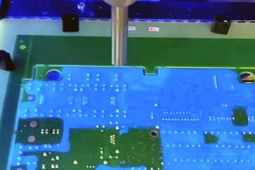
Wave soldering is a soldering process used in PCB manufacturing. SMDs are glued onto the surface of the PCB by placement machines before running through the solder wave. Overall, this process is ideally suited for the bulk production of PCBs. It involves utilizing a pump to produce an upsurge of solder that the PCB passes over. This pan of outpouring molten solder looks like a standing wave, hence the name. As the PCB contacts this wave, the attached components become soldered to the PCB.

There was a time that wave soldering was used for both surface mount and through-hole PCB assembly. However, a number of problems, including controlling the amount of solder for tight pitch leads on increasingly smaller components and the movement toward BGA and other under package connections, contribute to what is known as selective wave soldering. This is where regions, instead of the whole board, utilized wave soldering.

As of late, there is a systematic replacement of through-hole components with surface mount variants. Furthermore, as the designers are opting for surface mount components over through-hole, so is the landscape changing for soldering techniques. This, of course, means that reflow soldering is currently supplanting the use of the wave soldering technique. This is especially the case with the majority of large-scale electronics applications.

Note: Wave soldering is still the method of choice whenever it is not prudent to use SMDs, i.e., high pin count connectors, large power devices, or where through-hole technology is predominant. And this is the de facto method in use for soldering through-hole components onto PCBs designed for surface mount type components. This includes highly application-specific through-hole components and multi-lead through-hole components.

What is Reflow Soldering?

Using the reflow soldering process on PCBs containing a mixture of plated through-hole (PTH) and surface mount technology (SMT) components can be beneficial. The primary goal of the reflow technique is the achievement of the eutectic temperature by the solder paste, thus causing it to undergo a phase change into a molten state (liquid). Furthermore, it is at this specific temperature range that the molten alloy expresses characteristics of adhesion. Also, the molten solder alloy behaves much like water, but with properties of both adhesion and cohesion. Moreso, with adequate flux, while in the liquid state, molten solder alloys display a trait called wetting.

The Reflow Soldering Process

Reflow soldering is a process that utilizes a solder paste consisting of a sticky mixture of flux and powdered solder to attach tiny electrical components to their contact pads provisionally. Furthermore, once the attachment phase is complete, the process subjects the entire assembly to controlled heat. At this juncture of the process, the molten solder paste reflows, thus producing permanent solder joints. Moreover, the process accomplishes the necessary heating by one of the following methods:

Passing the assembly under an infrared lamp
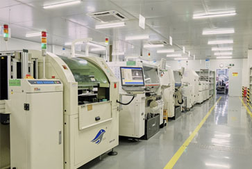
Passing the assembly through a reflow oven

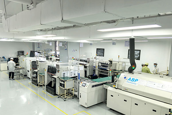
Overall, the reflow soldering technique with extended industrial convection ovens is the ideal process for soldering SMDs to a PCB. Furthermore, the various sections within the ovens have regulated temperatures that are governed by the thermal requirements of the PCB assembly.

The temperature profile for a specific PCB will permit the reflow of solder onto the adjoining surfaces, without damaging or exceeding the electrical component’s temperature tolerances. With the conventional reflow soldering method, there are typically four stages or zones that each possesses a distinctive thermal profile, as follows:

Stage 1: Preheat
At this stage, the primary goal is to preheat the assembly consistently and safely to a pre-reflow or soak temperature.

Stage 2: Thermal soak
This stage usually consists of 60 to 120-seconds of exposure to activate the flux and remove solder paste volatiles.

Stage 3: Reflow
This is where we reach the maximum allowable temperature, which is a crucial consideration. As a general note, a typical peak temperature lies between 20–40°C above liquidus.

Stage 4: Cooling
At this final stage, we gradually cool the processed PCB and solidify the solder joints. The effects of proper cooling prevent thermal shock or excessive intermetallic formation on the components.

Designing for Wave Soldering vs Reflow Soldering

As presented above, there are distinct differences between wave and reflow soldering. These differences translate into different design considerations, as shown below.

Wave Soldering Design Considerations
Spacing and clearances
Following good DFM spacing and clearance guidelines is always important, but more so for wave soldering as there must be ample clearance for the solder to flow between components and other surface devices.

Solder mask dam
Another concern is that the solder will flow over the solder mask dam. In this case, solder bridging or the connection between component pads that should be isolated will occur.

Component orientation
Achieving even flow is very important for wave soldering. By orienting components to support this will lead to better quality connections.

Reflow Soldering Design Considerations
Material thermal characteristics
For reflow, the board is subject to higher temperatures and for longer periods of time. This means that board thermal characteristics; such as CTE and dissipation are important considerations.

Improper Component and footprint alignment
If the component pins and footprint pads are not properly aligned a number of issues may result; such as tombstoning, where one side of the component is unattached, or a bad solder joint that may affect the amount of current flow into or out of the component pin.

Board deformation
As PCBs are subjected to high temperatures for extended periods of time there can be a possibility that the board will warp or crack. Therefore, the board material and construction must be able to withstand temperature cycling.

We now know that wave soldering is more suited for through-hole components, and reflow soldering is ideal for SMDs. To know more about PCB assembly, welcome to visit our website www.abp.net.cn or contact us via [email protected].